AT&T L-Carrier Cable Network
In the period between World War II and the divestiture of the Bell System, the tremendous growth of telephone traffic in the US, along with the need to distribute TV programming for the networks resulted in the construction of a nationwide grid of long distance telephone facilities. Three primary media were used for this: analog carrier on paired wires (cable and open wire); analog carrier on bundled coaxial cable; and analog carrier on microwave radio. This page describes the hardened L-carrier routes which were designed to skirt areas targeted by Soviet nuclear weapons. The switching and repeater stations along these routes were built underground and equipped with air filters, radiation protection, food and water to allow their crews to operate through and after an attack.
As of 1974, coaxial systems carried 30 percent of interstate traffic over more than 20,000 route miles of cable. Different carrier systems were used, but the latest, the L5 system could carry 108,000 simultaneous conversations. Of the balance of the interstate traffic, 69% was carried on microwave radio routes, and the remaining 1% on copper paired wire cable and open wire systems remaining in very remote rural areas. Since this time, almost all traffic has moved to digital systems on fiber optic cables.
Nuclear hardened coaxial cable routes were constructed in the 1960's and 1970's, with major routes linking the east and west coasts, along the eastern seaboard, and from the east to the midwest. I am in the process of visiting as many sites as I can in the midatlantic region and posting photographs and current and historical information here. Please contact me if you have any information or photos of any of these or any related sites.
Mid-Atlantic L-Carrier Stations and Cable Routes
These were main stations providing circuit routing and power injection to the cable. Repeaters were located every mile or two along the route in underground manholes. The cable itself was buried a minimum of 4 feet deep. The spacing of the repeaters and main stations depended on the version of the L carrier system in use on a particular route, the location of cities to be served by sidelegs from the main cable, and geography of the area. Different classes of stations provided either just power feed, circuit termination, and circuit switching. The power feed only stations were the smallest, while the switching stations were quite large, and all located below ground for protection from nuclear radiation and blast effects. The stations were constructed of reinforced concrete and had heavy steel blast doors.
The coaxial cable itself consisted of a number of pairs of coaxial tubes, each 0.375" diameter. L1 had 4 pairs of coaxial tubes in one cable sheath and L5 had 11 pairs...see the table in the L5 section below for more information on the cable system capacities.
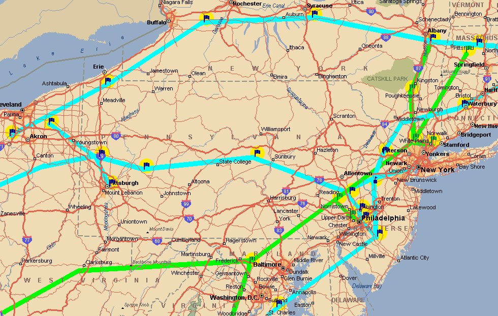
The map below shows most of the hardened stations in the mid-atlantic region, along with some of the sideleg and unhardened locations in cities adjacent to the routes. A typical pattern is that each route had one or more main stations near each city it served, for example, Pottstown, PA served the Philadelphia area on the Airmont-Monrovia north-south cable route, while Finland served Philadelphia on the Cherryville-Lillyville east-west route.
On the map below note that there are two primary north-south routes linking the major cities of the east coast, one in blue and one in green. There are also three east west routes, one through New York state, one through Pennsylvania, and one through Maryland. The Maryland route, originating at Monrovia, continued all the way to Los Angeles, California, with the final hardened station on that route at Mojave, CA. The Pennsylvania route, originating in New York, passed through Cherryville, NJ ( a major switching station) and ended at Hillsboro, MO. The New York State route originated in the Boston area and went to Chicago, IL, and beyond...possibly serving as a northern route to the west coast (I do not have maps showing this route beyond the Chicago area, although maps do indicate it continuing past Chicago).
Click on a station to view pictures and information. (Stations are being added as they can be visited)

First Commercial L-5 Route:
Lillyville, PA to Hillsboro, MO
L5 was the last version of the analog L carrier to be used in the Bell System. The majority of the coaxial routes were never upgraded beyond L4 because of the introduction of fiber optics in the late 1970's.
Capacities of the L-carrier types are shown here:
| Designation | Voice circuits per channel | 2-Way channels per
route (including backup protection channels)
(this is also the number of pairs of tubes in the cable) |
Total Route Capacity |
| L1 | 600 | 4 | 2400 |
| L3 | 1860 | 6 | 11,160 |
| L4 | 3600 | 10 | 36,000 |
| L5 | 13,200 | 11 | 145,200 |
(click on map for larger version)
Terminal Main Stations:
Other L Carrier Stations:
Map of Pennsylvania L5 Stations
Most were built for L4 and later upgraded to L5. The L5 route was expanded to the east through Finland and Cherryville into NYC. Pottstown also was a #5 Crossbar Autovon switching site. Hillsboro, MO and Cherryville, NJ are also the sites of #4ESS toll switches.
Alphabetical Listing of L Carrier Stations
Airmont, NY Cedarbrook, NJ Cherryville, NJ Elderton, PA Finland, PA Hillsboro, MO Laurelton, PA Lillyville, PA Morgantown, IN Pottstown, PA Tully, NY Xenia, OH
Bell System Reference Frequency Distribution Plan
(click on map for larger version)
Links to other sites on this topic:
Mark Foster's excellent L Carrier site.
�2003 Michael W. Jacobs. Commercial use prohibited