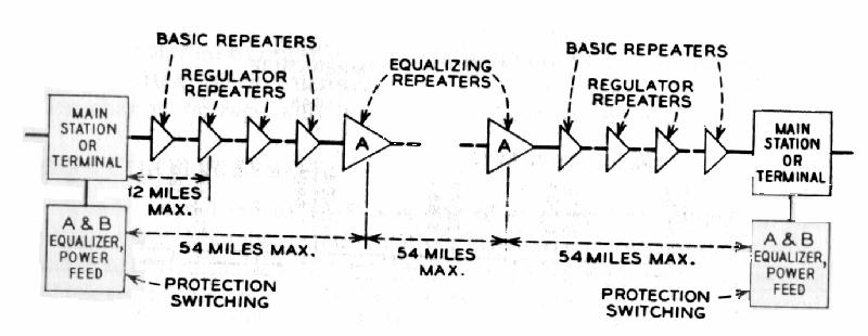
For technical reasons these L-4 centers existed every
150 miles in the cable route (buried repeaters existed every 2 miles).
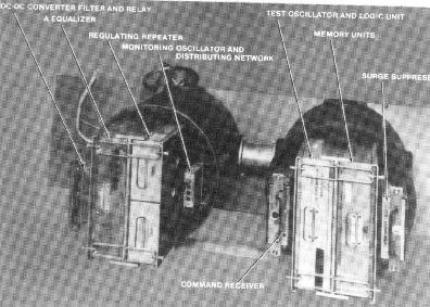
The repeaters were buried every 2 miles. A typical repeater for one coaxial tube is shown below.
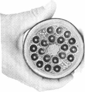
Across section of a piece of L-4 coaxial cable is shown below. This is a 20 tube cable. Copper wires in the middle are for signaling and order wire circuits, alarms etc. Each tube could carry 3600 voice circuits. The cable was incased in a lead sheath and weighed 11 pounds per linear foot. The cable was buried 4 feet deep to insure that it stayed at 50 degrees F regardless of weather. Changes is temperature adversely effected the cable electrical characteristics.
TWENTY TUBE COAXIAL L-4 CABLE
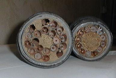
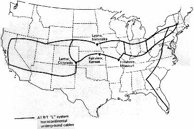
The top photo is a 20 tube coaxial cable held to show relative size. The lower photo is a 20 tube L-4 cable placed next to a 12 tube cable that was formerly part of a L-3 system. The original route ran from Massachusetts to Miami. Then across the country to CA and many other routes followed to insure redundancy (four separate routes served Cheyenne Mountain to insure communications). Several of the major cable routes are shown below.
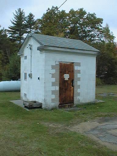
Repeater site at Hubbardston, MA. The repeaters were below grade in the vault that looks like a foundation for the building. This one is owned by a gas station and used for storage. The owner bought it from AT&T in the late 70's. See addition photos of repeater facilities.
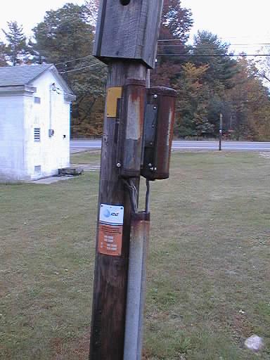
Cable marker next to Hubbardston repeater facility. Not bird house on top (probably not Western Electric issue). Also note two devices on side of pole that hold test points for order wire contained in L-3 cable.
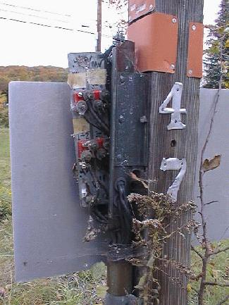
Closeup of test points on the L carrier order wire. The technician would use a 100A portable battery powered test set to attach to the test points. Using the 100A test set a fidle technician could talk to the main station or another technician. The 100A tst set was designed to talk up to 54 miles. (The order wire circuits in a L carrier route are supplemented by repeaters at 54 and 108 miles). This particular repeater station had 2 test points (east and west). A second pair of test points is inside the repeater vault.
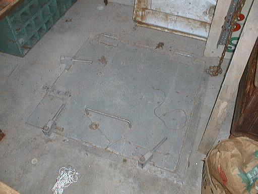
Open the door and the hatch to the vault is on the floor. Well secured by key and latches. This vault was filled with water. Repeater huts had commercial power fed to them for use by the technician. Power was needed for the blowers necessary to ventilate the vault before use, lighting and an occasional pumping. Remote facilities required the technician to bring a generator along. Some remote sites required snowmobiles in the winter to tow the generator, blower and test equipment.
L CARRIER CABLE MAPS
The following map show key routes for the Department of Defense's communication's system during the Cold War.
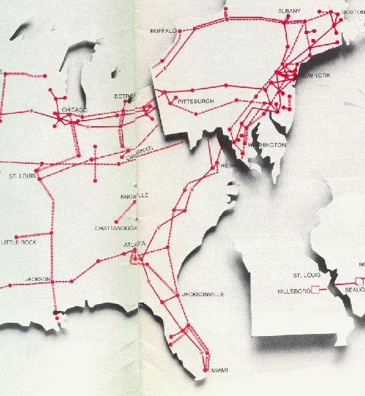
A detailed map of the L-Carrier system in 1973 for the Eastern United States is shown below. Solid lines are L-4 cables/routes dashed lines are L-3 cables/routes. Fuzzy lines (/////////) are L-1 cables/routes.
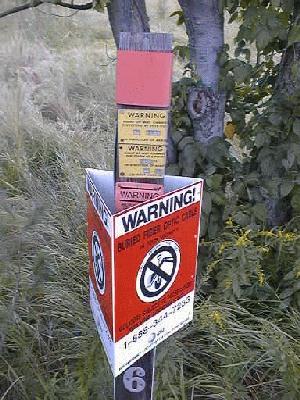
Many of the routes were marked to show the utility right of way. This old L-4 cable marker assumes a new life a a fiber optic cable maker. Beneath the new colored warning sign a faded sign reads "WARNING DO NOT DIG TRANSCONTINENTAL CABLE". This marker is on the Littleton, MA to Blackstone, MA L-4 cable route.
These facilities also supported many other related military
communications matters including inter connectivity with Presidential as
well as other military aircraft, the NAWAS warning net, the SACDIN warning
system, Civil Defense key circuits, nuclear detonation detection, an other
systems. To the best of my knowledge the system was dismantled in
the mid 80's. Break up of the bell system as well as the introduction
of fiber hastened the demise (not to mention the fall of the Russian empire).
Currently many of these centers have an after life supporting cellular
telephone antennas on their little used microwave towers (Most of the huge
cornucopia antennas "turned down" as inefficient and expensive to maintain)
and also serving as hubs for fiber cables that have supplanted the old
L-4 cable that existed in thousands of miles of Bell System right of way.
SYSTEM CAPACITY
SYSTEM
DATE BANDWIDTH
COAXIALS REPEATER
CAPACITY
PER CABLE SPACING
L-1
1941
3 mhz
4
8 miles
600 voice circuits
L-2
1942
840 khz
4
16 miles
360 voice circuits *
L-3
1953
8 mhz
8
4 miles
5,580 voice circuits
L-3 (Improved)
1960
8 mhz
12
2 miles
9,300 voice circuits
L-4
1967
17 mhz
20
2 miles
32,400 voice circuits
L-5
1972
57 mhz
22
1 mile
108,000 voice circuits
* Only one L-2 Coaxial System was installed between Baltimore and Washington. The outbreak of WWII mothballed the L Carrier system bring this system development to a halt. Rapid economic development after the war made the L-2 system obsolete.
Note: Currently a single fiber cable can
carry 3,200,000 voice circuits.